CFD - Hull and appendages
|
Since 1992, CRAIN has been the pioneer in CFD (Computational Fluid Dynamic) applied to sailboat design. This activity is based on a permanent collaboration with LHN in ECN (Naval Hydrodynamic Laboratory in Ecole Centrale de Nantes - a top engineering school), in which CRAIN has evaluated the following ECN codes : REVA, AQUAPLUS, ICARE. This collaboration, combined with tank test and wind tunnel results, has led to :
CRAIN also uses aerodynamic codes to study bi-dimensional flow around foil section and tri-dimensional boundary layer around hull and bulb. Where generalist RANS (Random Analysis Navier Stokes) codes work better, CRAIN is able to provide adequate specification to its partner in charge of computation. Aware of CFD limitations, budget constraints and delivery time in nautical project, CRAIN insists on :
|
 |
REVA : canoe body drag and appendage efficiency with potential flow
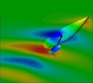
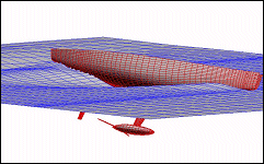
Code REVA solves potential flow with free surface around hull with appendages. Developped by Gérard Delhommeau from ECN (Ecole Centrale de Nantes - Engineering school), REVA computes ship drag taking into account free surface deformation (wave resistance) and induced drag from appendages. Meshes are surfacic, this allows reduced meshing time and reduced computation time. Article [French - PDF 181ko]REVA's main limitations are :
|
 |
|
Therefore, the following effects cannot be taken into account :
Our experience allows us to promote REVA for problems such as :
The opportunity to explore wave and pressure fields, to get efforts on each mesh element, give a mean to perfect shapes through a controlled process. |
 |
ICARE : turbulence, free-surface, unsteady flow
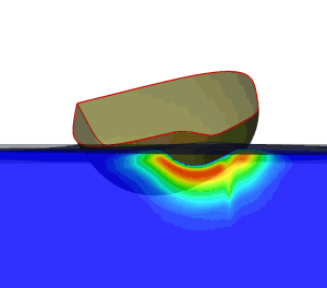
This code developed by Bertrand Allessandrini from ECN is among the unique software applications including both a RANS method and a free surface condition. Used since 2000 by CRAIN, ICARE has already allowed us to fill two major gaps in REVA :
These capacities have been used to optimise, with a success confirmed by tank test, aft shape and buttock slope of Le Defi 2003 IACC (French Challenge for the America's Cup 2003). CRAIN has optimised mesh and computation parameters for canoe body evaluation, so we can now carry out studies within acceptable means and time. ICARE offers large possibilities, since viscous flow around hull and appendages can be carried out with variable speed, heel or heading. Various ICARE applications are under developement at CRAIN :
|
 |
XFOIL and 3C3D : foil section and shape boundary layer computation
Since 1993, CRAIN has been designing foil sections and bulb shapes with a numerical method combined to experimental validation.
These precautions allow us to make the right hypotheses on ambient disturbance level, which dramatically influences foil section optimisation. So, we have successfully designed :
for IACC monohulls, ORMA multihulls, IMS monohulls, dinghies,...
Industrial RANS : appendages viscous computation
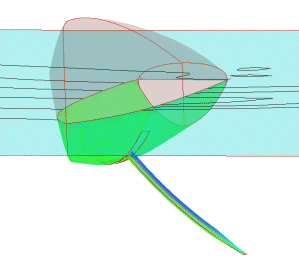
RANS solution and industrial meshing programmes are suitable when neither free surface, neither laminarity or junction interaction are part of the problem. In that case, CRAIN entrust meshing (using ICEM) and computing (using RADIOSS) appendages configurations to MCube company. Meshing hypothesis leading to realistic lift and drag values have been deduced from wind tunnel results. |


